Wolseley Hornet: "Crossing the T's and Dotting the I's" (Please Click to Open)

 After an endless period of finishing and detailing we seem to be running out of items on the finishing list and... better still, we do not seem to be adding quite as many.

The time consuming work of a restoration goes without saying but the time consuming work in a prototypical creation and restoratrion project is exponential!

We have experimented, designed, altered,adapted, fitted new designs and trialed so many components throughout and now it all comes to a point of focus as we are near complete on the rolling chassis / body (presently delayed with the post summer Lockdown regulations in Wales and latterly England) and now we are close to the engine test run.

Although we had not expected any problems we felt it prudent to run through the supercharger and generally refresh this with new bearings and any fettling that might be necessary. With new bearings and a little dressing of a few areas we can check and set the various clearances, dress the gears and reassemble a known entity. We have made a small modification to allow the oiling of the front lower bearing, although the bearings are sealed there is some evidence that this bearing might suffer from the remains of fuel and condensation which over a period ingress into the rubber seal. I can imagine that the original design of this unit may have been to pump air alone as opposed to the fuel mix it endures during its racing career. We have also made some repairs with the use of thread inserts where necessary.

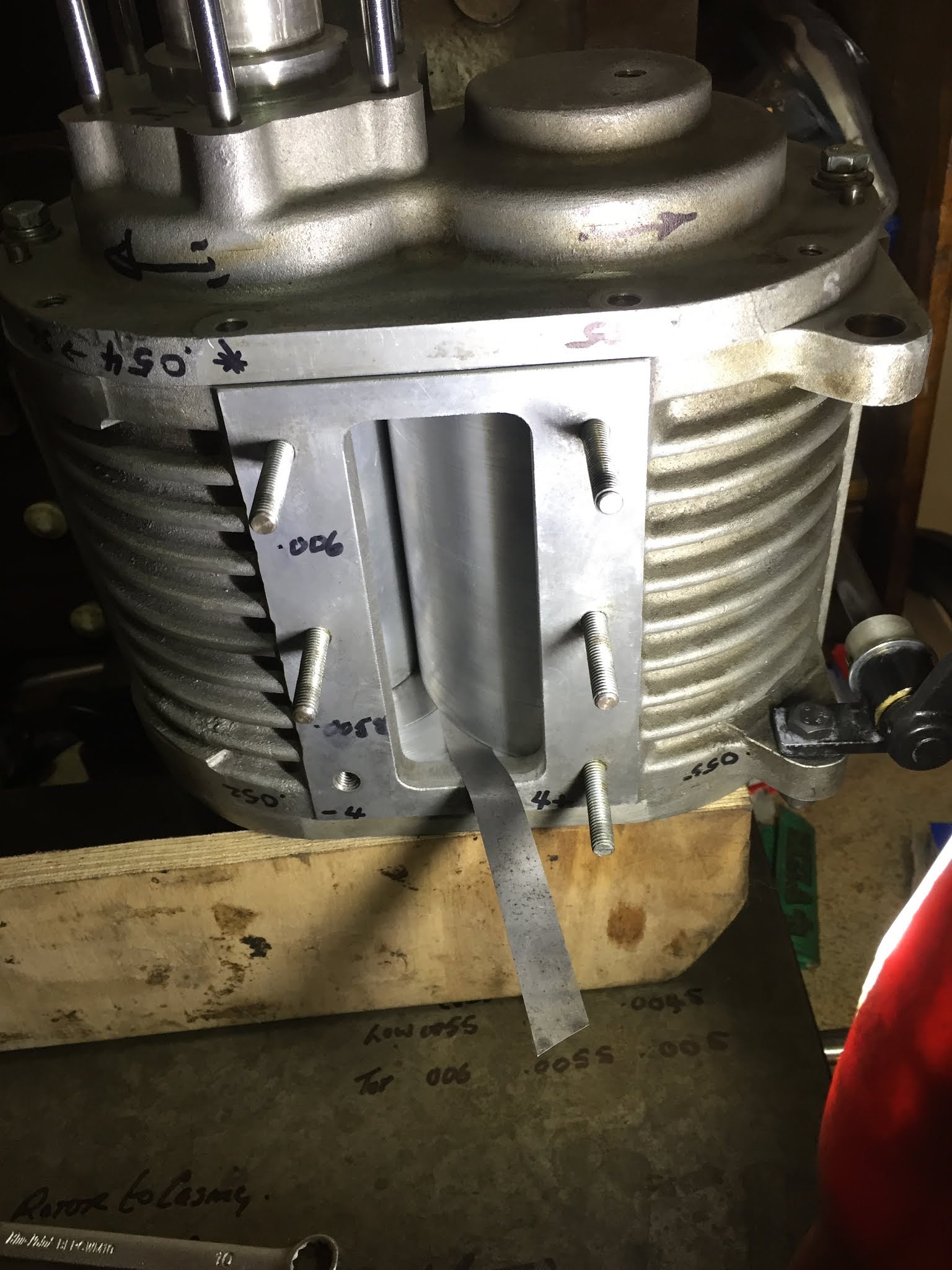
The supercharger is actually not as simple to set end face clearances as you might think. The rotors are floating axially and thrust washers dictate their position in the endplate counterbores whilst the rotor end face clearance is a factor of the housing length and rotor length. A lot to consider when measuring.

All bench measurements are noted to a chart to help us to monitor the unit during the initial period of testing. We have taken the clearance measurements over a set range of temperatures to provide us with an initial reference.

The gears that mesh the rotors are straight cut... very strong, and mounted via tapers not keys. There has been some discussion in the vintage world regarding the use of tapers and the fact they might fail as opposed to a key. My own feeling is that tapers are very good, providing they are appropriate for the design loads, in perfect contact and assembled spotlessly clean (including the absence of Loctite). A taper might just provide the first point of release should something catastrophically fail within the rotor and send ever churning fragments into your engine as a drive chain or gears soldier on!

We have also made a metering unit to replace the now rare original item that controls the oil feed to the valve train. As engine speeds increase with new materials and designs, we may consider a different oiling system at a later date to ensure that the high loads induced by a sporting camshaft are appropriately accommodated by adequate lubrication.


Rizla: For generations engineers have been using the precision of Rizla papers! I am proud to pass the tradition to Jacob...




A new locating dowel machined and fitted by Jacob.


During pressure testing of the head oil supply, we had to confirm all areas are receiving an adequate amount.


The oil delivery metering unit for testing. Alongside you can see the 3D printed item Jacob used to prove his the initial CAD design.


Peugeot 401 Progress


 Recently we have been making good progress on the Peugeot 401 including completing the timing. The rear main bearing housing has been bolted and and marked, a gasket was made for the oil return screw cover; using engineering blue to leave the outline on the gasket paper to allow an exact cutting line.

Timing

Once this was fitted the bell housing and flywheel could be bolted on. The Tipex is used as a quick identifier to highlight that bolts/nuts have been torqued up. 

When preparing to set the cam timing for an engine of this age, we often don't trust timing marks as so many have been added over the years, and parts have been altered. Therefore first principles are used, hence the timing disc shown on the flywheel. This allows us to set all the timing confidently, and precisely. 

Exhaust/Intake Prep

As this engine is not being built for concourse, we aim to keep the gloss paint to a minimum so that it blends in when fitted back to the lightly refreshed car. This is demonstrated on the exhaust/inlet manifold and corresponding fittings. The manifold and fittings were wire brushed and cleaned to remove all loose rust and oil, then were treated with high temperature paste, which leaves a very nice OEM sheen, not glossy but certainly much tidier than rust! 

Oil Filter and Water Jacket Covers

This Peugeot is fitted with a very nice oil filter assembly, consisting of a external housing with a very styled metal mesh filter. That certainly is Art In Engineering! additionally the oil pressure relief valve is built into this assembly. This required a gentle tap out along with some heat, and then a light oil stone on some burring and rust spots. 

The housing was repeatedly and thoroughly washed through to remove all the years of oil build up and sediment! Many years! Eventually it began coming clean and was ready for paint. 

 The cap flats were dressed to recover them as best as possible, aswell as the housing bolt faces being oil stoned ready for refitting.

J.


Click here to see Supercharger assembly clearance tests. (more to follow)


We are sorry, Google no longer supports the video format, the videos will be uploaded to you tube asap. (DEC 2020)


P51 MUSTANG 4 SHIP FORMATION FLIGHT!

Autumn Wolseley Hornet Special. Please click here to open.

Wolseley Hornet.

Supercharger work, fettling and prepare for new bearings and an extra oil feed provision for racing and to help with a fuel / air mix travelling through rather than a dry "air only" charge.


Tough to remove gears mounted on tapers. Lots of patience required as this is such a precision engineering piece with no tolerance of heavy handed work.


Oil pipe recovery, removing and old section and replacing with another modified four way union and tricky 90 deg bend.


Ready for final test fit and final silver solder.

Below: here we are making the real version of the 3D printed oil regulating valve illustrated on the previous post.


Wolseley Hornet Spl Details through September... Superchargers!

On the Bench:

 Here we have been working on superchargers. With some preventative maintenance replacing the hard working bearings and a general checkover. We also have a Volumex to attend to in the same way.


The Wolseley crankshaft has been heat treated, unfortunately without careful masking, keyways and drillings become undersize. Here we are carefully filing and oilstone dressing to make special stepped keys before completing the front section. Initially we used loose keys to aid with the repeated test assembly and setting of gears and sprockets, now it is the final detail that counts.


In the previous post Jacob designed a little oil metering device for the Wolseley on Autocad and 3D printed this prototype. We are testing to gauge the oil feed and flow rate and can now proceed to machine the real thing with only a few changes to the reduced channel section, making it a little more robust.


We have changed to a different gearbox on the Wolseley and so we have altered the first pair of clutch withdrawal fork bushes which were made in Oilite material, they now fit the replacement gearbox. By making bronze sleeves we have been able to re use the Oilite in the slightly larger bell housing. After machining we give each bush a light heating process and then soak in oil until required.


Supercharged Wolseley Hornet Spl and Triumph 2000 bits and pieces. [Please click here to fully open]

 The Wolseley is to have a bespoke oil regulator to allow adjustment of oil flow to the cylinder head. Here Jacob is designing the arrangement with CAD to allow him to print an initial plastic model of the prospective design. The time to CAD something as straight forward as this flange and adjusting screw is very quick and the printer works away whilst we are working elsewhere. However, to have the final mock up in your hand is very helpful before machining the real thing in the lathe.


Please note these drawings are in an early stage, they do not yet reflect the finished item.

Here we have been working on the floor transmission cover sections to provide steel protection should the propshaft ever come adrift during racing.


The cockpit is very "compact" in the Wolseley, especially in the footwell. We have had to care fully design an arrangement to connect the throttle to the carburettor via a series of linkages, sometimes with some tricky little additions.

We avoid altering braking items as much as possible but in this case we have little choice. The brake fulcrum assembly has been repositioned by a small amount and the connection to the push rod will now be via a rose joint. Here we have calculated the loads expected through the brake pedal plus a 40% + safety margin to ensure the joint and bolt, which is now under a single shear load, are substantial.

Throttle pedal link to exit from the side of the pedal.


New brake push rod to accept a rose joint (note the nose is yet to be cut to length an machined to a radius or rounded end).


Brake lever load calculations.


Machining Brake lever spacers to reposition the assembly.


Triumph 2000:

Here we have been de scaling the cooling system and fitting a new radiator and water pump to improve the summer cooling on this amazing condition, original car.


Supercharger Adaptation Continued.

 Some more Supercharger drive over the last two weeks. All very time consuming as the clock races as if supercharged toward Christmas!