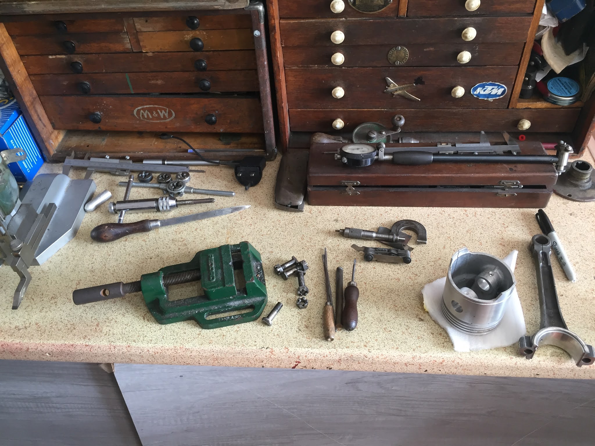
Supercharged Wolseley Hornet Spl and Triumph 2000 bits and pieces. [Please click here to fully open]
The Wolseley is to have a bespoke oil regulator to allow adjustment of oil flow to the cylinder head. Here Jacob is designing the arrangement with CAD to allow him to print an initial plastic model of the prospective design. The time to CAD something as straight forward as this flange and adjusting screw is very quick and the printer works away whilst we are working elsewhere. However, to have the final mock up in your hand is very helpful before machining the real thing in the lathe.


Please note these drawings are in an early stage, they do not yet reflect the finished item.
Here we have been working on the floor transmission cover sections to provide steel protection should the propshaft ever come adrift during racing.


The cockpit is very "compact" in the Wolseley, especially in the footwell. We have had to care fully design an arrangement to connect the throttle to the carburettor via a series of linkages, sometimes with some tricky little additions.
We avoid altering braking items as much as possible but in this case we have little choice. The brake fulcrum assembly has been repositioned by a small amount and the connection to the push rod will now be via a rose joint. Here we have calculated the loads expected through the brake pedal plus a 40% + safety margin to ensure the joint and bolt, which is now under a single shear load, are substantial.


if you have or are considering a project, please read this article: "Some Engine Build Considerations" using the Peugeot as an example. [Please click here to open]
I often have a long conversation with inquiring enthusiasts about engine build stages and methods.
Even though I have many years of engine building experience, especially with engines of the 20's and 30's, of which there have been over 70 different types, I can still underestimate the time taken to complete a build. I am lucky to have had many understanding customers but, nevertheless, I often find myself working free of charge in an effort to to keep costs under control. This is to be expected and is not something that I generally object to as it is part of my chosen craft.
As we are building the mid 30's Peugeot 401 engine at the moment, I will use it as an example. It is important to say the Peugeot is very typical of the problem solving exercises that we might encounter with an 80 to 100 year old engine. The Peugeot is certainly not a bad example, I have used it simply to illustrate my point as we encounter many projects that are very poor in comparison to this example.
On all projects compromises are often made and to this end it is important that we keep the overall project picture in mind. We consider if the engine is to be revved and loaded as in a racing engine or simply as a very easy going saloon car. Will it be possible to gather replacement parts, or do we use second hand or make new? How big might the budget be and how valuable will the car be at the end? Indeed is the value of importance for the particular project in hand? This and many questions are all to be taken into account.
For this reason, I do not judge when I view a finished article at a show or as a box of parts presented to me. Whether it has been just sufficient to safely save the project for future generations or has been a multi thousand pounds restoration by a professional company; we must always respect the original brief and budget that might have been in place.
The Peugeot 401 will not be high revving with high component loads, it will be a nice period car that will be driven and nurtured with respect to the 85 year old components.
Now we look at the build itself or at least part of the build, since we have this example on view at this point. In this case, we have converted the big ends to modern shell bearings. Whilst this is not a cheap exercise, the cost will be similar to re white metaling, it will benefit the reduced complication and expense and to future generations or later rebuilds.
As with all conversions, we have to consider any consequence of modification. Almost all alterations have an affect somewhere along the chain. With the Peugeot we had to take time to carefully produce locations for the shell tangs and the previous engineering company machined the conrods, taking care in providing intricate white metal side face extensions to retain the con rod lateral position.
Now we move to the individual components and the actual process of the conrod and piston fitting. It is easy to relate to a classic period engine (Morris Minor, Ford Cortina etc) when you think through the fitting of pistons and rods. You would simply clean and fit the piston to the conrod and fit two gudgeon pin retaining circlips. You might then thread the assembly down through he bore with the aid of a ring compressor and carefully torque the caps into position on the crank shaft. Four can be fitted within the hour.
Now consider this earlier period engine:
- The conrod has an oil squirt hole, be sure to align with the thrust side (having drilled the new bearing shell to suit.
- The gudgeon pin is a very tight fit into the conrod and into the piston, it is retained by a bolt and nut locating via a groove in the waist of the gudgeon pin. The whole assembly is very tight. By freezing the pin and warming the rod and piston you may be able to press them together and align the bolt, but it is a very tricky operation. Perhaps the machining of a round nosed gudgeon pin guide will help to fit and align before the temperatures become equal and everything sticks!
- The small end bolt must be tightened having been pre-fettled to make sure there are no burrs or radii clashes to hold the head away from the rod. The securing castle nut must align the slots with the split pin hole exactly, if not, remove and dress the underside of the nut until perfect alignment is achieved when tight. Fit and neatly turn the split pin..
- Piston? Well it is likely that this is an old batch that has come to light or perhaps an unknown make and quality. Even some of the better known manufacturers have faults, some are willing to work and support you in order to improve their product. Some are more dangerous, denying flatly that you have found a fault even as it comes out of the box.. Remember, all of the responsibility for failure will be directed to the engine builder until proven otherwise, we must cross every "t" and dot every "i" and more at every stage.
- Now, having fettled conrod bolts and conrod / caps for old destructive ID markings (including heavy centre pop marks and even hacksaw cuts denoting the cylinder number...), burrs, bruising and any tell-tale of stretch in the bolt (I am not including high risk and high stress engines which should have replacement bolts manufactured). It is now time to consider a locking method other than the original design, much criticised, locking tabs (which, incidentally lasted 80 years in a simple low stress engine with little problem in most cases). And now to torque the big end bolts, but if they are of a certain design nut and bolt or stud, then you should consider measuring their stretch (increase in length) under load, a very accurate method of the period and even today as you can see the effect on the bolt regardless of thread lubrication or beneath the head friction. If they are nut and bolt with a split pin, each nut must be dressed to align with the split pin hole when tight.
- Piston and rod assy' fitting... not quite as you might expect, no dropping the assembly down through the bore as the classic period engine. Often during this 20 / 30's period the conrod bigend exceeds the bore diameter. And so you have to consider: 1) Fitting the conrod from the bottom until it protrudes through the bore and then fit piston and circlips and rings, but in the case of the Peugeot that is not possible as the gudgeon pin pinch bolt has to be assembled on the bench. 2) In some cases, you cannot get to the cylinder bore to fit the piston from beneath because of restriction in access from the crank. Therefore, they have to be fitted before the crank (you hope you remembered this before fitting the crankshaft!). 3) Fit the piston and rod assy from underneath having carefully cajoled it around the fitted crankshaft, push it up until it protrudes through the top of the bore, fit the rings, compressor tool and drop it back down the bore. As a note, often the crank is threaded into position (with the bearings mounted on the main journals), from the end of the crankcase / block ie. it does not have main bearing caps that allow you to simply "drop" it in and out of position as with the classics.

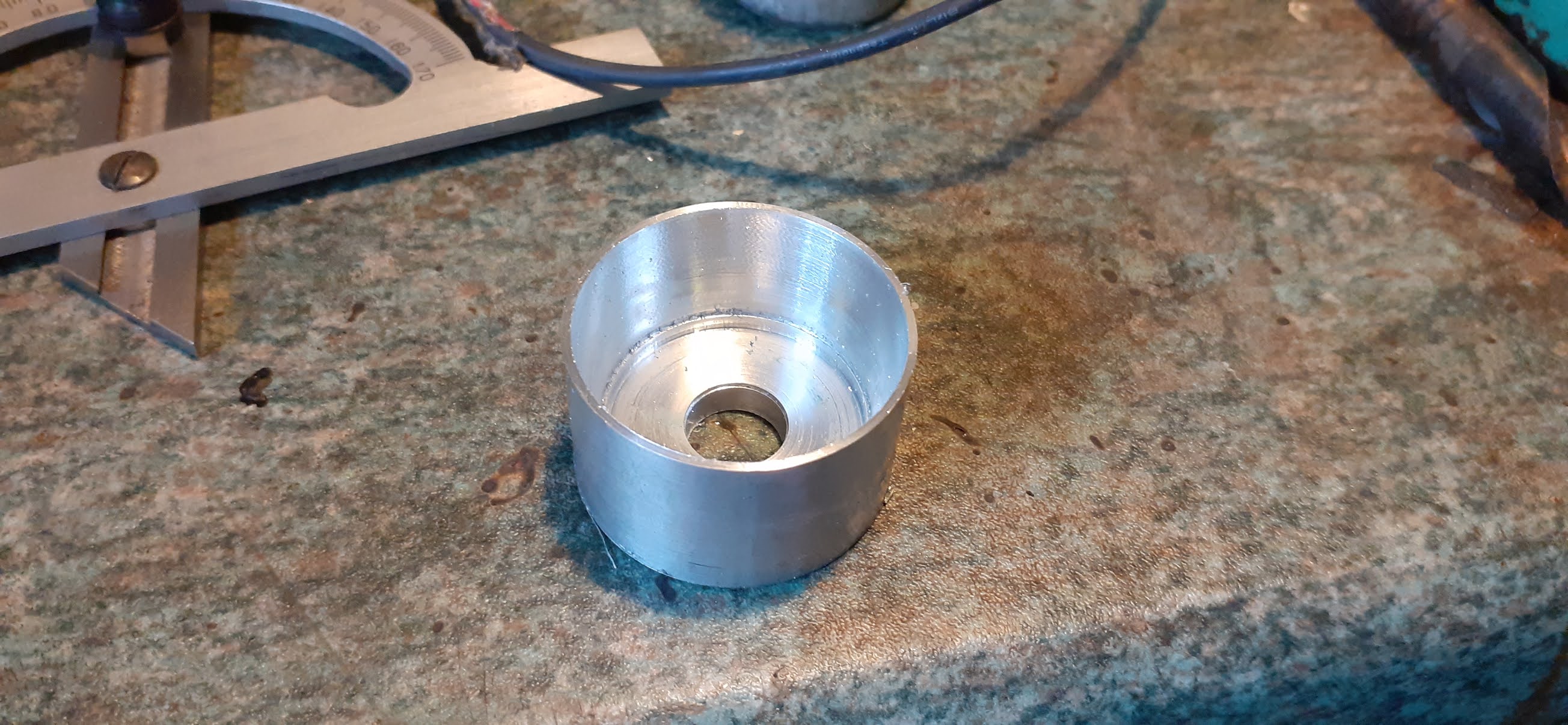
 Here the shell is sitting on a mandrel, mounted in the machine vice for careful drilling followed by de burring and an oil stone of the backing to ensure absolutely no high spots.


'30s Peugeot 401 Engine Build ........ Please Click here to open.
We have been assembling the Peugeot engine. Some final measurements of clearances, as it has been converted to modern thin wall shell big end bearings rather than the original white metal bearings. We have retained white metal main bearings. Here we are test fitting the conrods after extensive work. We have also rigged a temporary pressurised oil delivery to check all internal galleries and bungs as well as a final check of oil delivery to the "bottom end" J


Standard Vanguard Progress..........Please click here to open.
We have been making some good progress on the Vanguard. Since the carburettor rebuild with the new bushes, it fires to life every time! Sadly though, with a project of this nature, new things have been found as we progress, such as sticking brakes and a lack of clutch.. but it did see the light of day for the first time in 5 years!


Wolseley Late Summer progress Please click here to open
Some snippets into the progress on the Wolseley Hornet Special!


Supercharger Adaptation Continued.
Some more Supercharger drive over the last two weeks. All very time consuming as the clock races as if supercharged toward Christmas!
